


Avoid Unexpected Outages with Regular Testing
Regular testing of transformers can help identify problems that reduce system performance and can lead to unexpected outages. The dc resistance of a transformer winding can indicate the internal temperature of the winding when the resistance at ambient is compared to the hot resistance. The ideal test method is to make resistance readings at one minute intervals as the hot winding is cooling, using a unit like a Megger DLRO10HD 10 Amp Digital Low Resistance Ohmmeter. When this data is charted, the resistance at time zero can be estimated.
The typical test will indicate excessive overheating in the coils due to fatigue or corrosion of the internal coil and/or the internal connections. Low resistance testing on transformers addresses small, medium, large single, large poly-phase and auto-transformer windings. Tests are performed on:
- Dual windings with the test current connected through the windings in opposed polarities.
- Wye to wye windings with and without a neutral connection; the leg of the other winding is connected to the potential lead to measure the voltage at the internal connection.
- Wye to delta windings; a jumper is used to connect the current from the wye winding to the delta winding (this test mode reduces the test time).
- Delta to delta windings; the test time can be improved by connecting the current jumper to the primary and secondary of the same phase in opposed polarities.
Taps are used to improve voltage regulation and are adjusted daily. Excessive wear and loosening due to vibration can be identified with low resistance measurements. Consecutive tests can be performed on secondary tap changers (shorting style of taps). Large transformers have many tap positions and test time will be reduced, as the test current does not have to be shut off between tests. Tests on primary taps (open taps) must be performed as individual tests with the test current shut off between tests.
The low resistance ohmmeter must have sufficient current capacity to saturate the windings. The testing time will depend on the available test current. Large transformers require special attention prior to performing the tests. The insulation between the windings will store energy, similar to the dielectric in a cable, and must be discharged before a test can be performed.
When testing three-phase transformers, interaction will occur between the primary and secondary windings. This situation will be most evident when testing transformers with wye and delta windings, and can be minimized by connecting the test current to flow through both primary and secondary windings. The net effect is to reduce the mutual coupling between the windings and minimize the flow of circulating current in the delta winding.
Test current should be limited to the magnetizing current, which is about 1% of the full load current. The lower test currents reduce stress in the magnetic core of the winding. Large test currents produce large forces on the core and may cause damage.
DC Motor Bar to Bar Testing
Helical spring point probes are used to measure the value of the bar to bar resistances of the rotor in a dc motor (see previous Figure 2). This test is typically performed at the 10 Amp current level with the typical coil resistance measurements in the 6000 micro-ohm range. These tests identify broken/loose welds or solder connections between the coils and commutator bars. The resistance measurements should remain consistent. Readings may be higher on a heated motor, due to the temperature of the coils. As the coils cool, the resistance values may drop to some prior reference value recorded at ambient temperature.
Figure 20 shows a lap winding, a style where the windings are connected to bars laying next to each other. To make a test, the current probe should be placed at the end of the commutator bar and the potential probe should be placed at the connection to the winding (the riser on the commutator bar). The operator measures the resistance of the windings between each set of bars being tested (1-2, 2-3, 3-4, etc.). In this example, there is a possible weak solder joint between bars 4 and 5, and a break in the coil between bars 12 and 13 (the instrument will indicate this as an open).

In Figure 21 (lap winding, 24 coils), all the coils are connected in series. The resistance of each coil will be measured with the resistance of all of the other coils connected in parallel. The primary question for the operator is what constitutes an acceptable reading for a specific coil (Rm) since the remaining 23 coils in parallel will lower the resistance of the coil being tested. For this example, we will assume that the resistance of the coil before insertion into the motor (Rc) was 1.00 ohm. The expected resistance can be calculated by the equation: Expected Rm = (Rc)(# of coils being tested)(# of coils in parallel)/(# of coils being tested + # of coils in parallel). In this example:
Expected Rm = (1.00 ohm)(1)(23)/(1 + 23)
Expected Rm = .958 ohm

Figure 22 shows a wave winding, another manufacturing technique for putting high resistance coils in a motor. In this example, the coil runs from commutator bar 1 to 6 to 11 to 16 and then loops back around the armature to commutator bar 2 (connected in series). When the operator measures between bars 1 and 2, he/she is checking the resistance of the wave wound coil (the complete loop). In this example, there is a break in the coil between bars 12 and 17. This problem will appear when measuring bars 2 and 3, since they are the beginning and end bars of the loop.

Figure 23 shows wave winding commutator connections to the internal coils and test probe connections to individual commutator bars. This is a simplified layout, as the heavy ring shows the series connections for all the coils in the armature. A dc motor will have a different number of coils depending on the horse power and the voltage rating. In this example (testing from bar #1 to bar #2), two coils are in series and nineteen are in parallel. If one coil is open in the ring, the measurement from bar #1 to bar #2 will be the series value of the two coils. If the test probes are across the open coil, the total resistance of the other nineteen coils will be displayed.

Download the complete article “Guide to Low Resistance Testing”
Megger DLRO10HD 10 Amp Digital Low Resistance Ohmmeter
JM Test Systems now carries the Megger DLRO10HD Low Resistance Ohmmeter.
- High or low output power selection for condition diagnosis
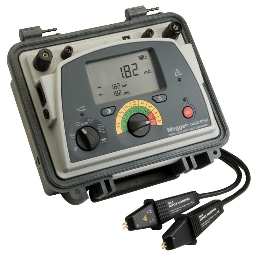
- Rechargeable battery or line power supply, continuous operation, even with dead battery
- 10 A for 60 seconds, less time waiting to cool, great for charging inductance
- High input protection to 600 V, inadvertent connection to line or UPS voltage will not blow a fuse
- Heavy duty case: IP65 lid closed, IP54 operational (battery operation only)
- Rotary switch selects one of five test modes, including auto start on connection, giving ease of use

Download the complete Data Sheet and Comparison Chart for the Megger DLRO10HD
JM Test Systems is a Stocking Distributor of Megger products
JM Test Systems has the Megger DLRO10HD for purchase
Rent the Megger DLRO10HD from JM Test Systems
Call us today for a quote at 800-353-3411 or contact us online.
Calibration Service – Since 1982 JM Test Systems has been providing NIST traceable calibrations to our customers. We are dedicated to a single goal: provide the best possible service for both our products and our customers.
ISO/IEC 17025 Accredited by A2LA ISO/IEC 17025 accreditation is your assurance that our work meets the highest standards.
