

Types of Equipment that Need Low Resistance Testing
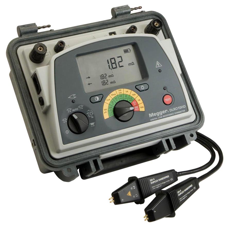
 Industries that consume vast amounts of electrical power must include low resistance ohmmeter measurements in their maintenance operations with a unit like a Megger DLRO10HD 10 Amp Digital Low Resistance Ohmmeter . Not only does abnormally high resistance cause unwanted heating, possibly leading to danger, but it also causes energy losses which increase operating costs; in effect you are paying for energy which you can’t use.
In addition, there are industries that have critical specifications on bond connections to ensure solid connections to “ground beds.” Poor connections reduce the effectiveness of the ground bed and can cause significant power quality-related problems and/or catastrophic failure in the event of major electrical surge.
Low resistance ohmmeters have application in a wide range of industries and can help identify a number of problems that could lead to apparatus failure. In general manufacturing industries, motor windings, circuit breakers, bus bar connections, coils, ground bonds, switches, weld joints, lightning conductors, small transformers and resistive components all require low resistance testing.
Typical Low Resistance Applications
Motor Armature – Armature windings can be tested to identify shorting between adjacent coils or conductors. Squirrel cage bars in the rotor can separate from the end plates, resulting in loss of performance.  If a motor appears to be losing power, a low resistance test should be performed. Alternatively, tests can be made when bearings are being replaced at a periodic or annual shutdown. Bar to bar testing on dc motor rotors is performed to identify open or shorted coils (see Figure 2). These tests are performed with spring loaded hand probes. This is a dynamic method to determine the conditions of the windings and the soldered connections to the riser on the commutator segments. When test data is reviewed periodically, the effects of overheating due to excessive temperature rise can be identified.
Power Generation and Distribution (high current joints, connections and bus bars) – Bus bars in a power system consisting of lap joints and other connections, are used to deliver  current to the elements in the system. These bolted connections can be degraded by vibration and corrosion. (See Figure 3.) The bolts are stressed to a specific tightness (torque), and the quickest and most economical way to determine the quality of the connection is to measure the resistance across the joint. The operator should have historical data to make the determination on the suitability of the connection. If left uncorrected, loss of power and/or excessive heating could lead to a meltdown at the connection.
Transformer Testing – Transformer winding tests are performed in the factory and then periodically in the field. The factory test is performed at ambient temperature. A second factory test is a heat run to verify that, at rated power, the resistance of the windings remains within its designed temperature rise characteristics.
Large transformers have “taps” on both the primary and secondary windings. The condition of the taps requires verification, since the secondary taps are operated daily and are exposed to excessive wear and vibration as the power distribution system balances the load carried on the various circuits. The taps on the primary side are critical to major adjustments in the power distribution and should be tested to ensure that a low resistance connection is available for the new power condition. Tap connections can corrode when not in use and may overheat due to the high current (which can result in a fire).
Circuit Breakers – Due to arcing at the circuit breaker pads, carbonized layers will build up and the live contact area will reduce or become pitted, leading to increased resistance and heating. This situation reduces the efficiency of the breaker and can lead to failure on an active transmission system resulting in the loss of a substation. When planning a test, the operator must be aware of IEC62271-100 and ANSI C37.09 for test current requirements. When testing large oil circuit breakers, the best instrument is one that ramps up current, holds it for a period of time and then ramps down. This test method reduces the magnetizing, which would otherwise be created by the sudden switching on and off of the test current. This can result in inaccurate “CT” measurements when the system is returned to normal ac operation.
Care should be taken when making a measurement across a CT as high dc currents may saturate the CT, desensitizing it to potential faults. Also, ripple on the test current may cause circuit breakers to trip. Careful positioning of the current probes should prevent this happening, and the ripple present on the current waveform may be minimized by separating the test leads.
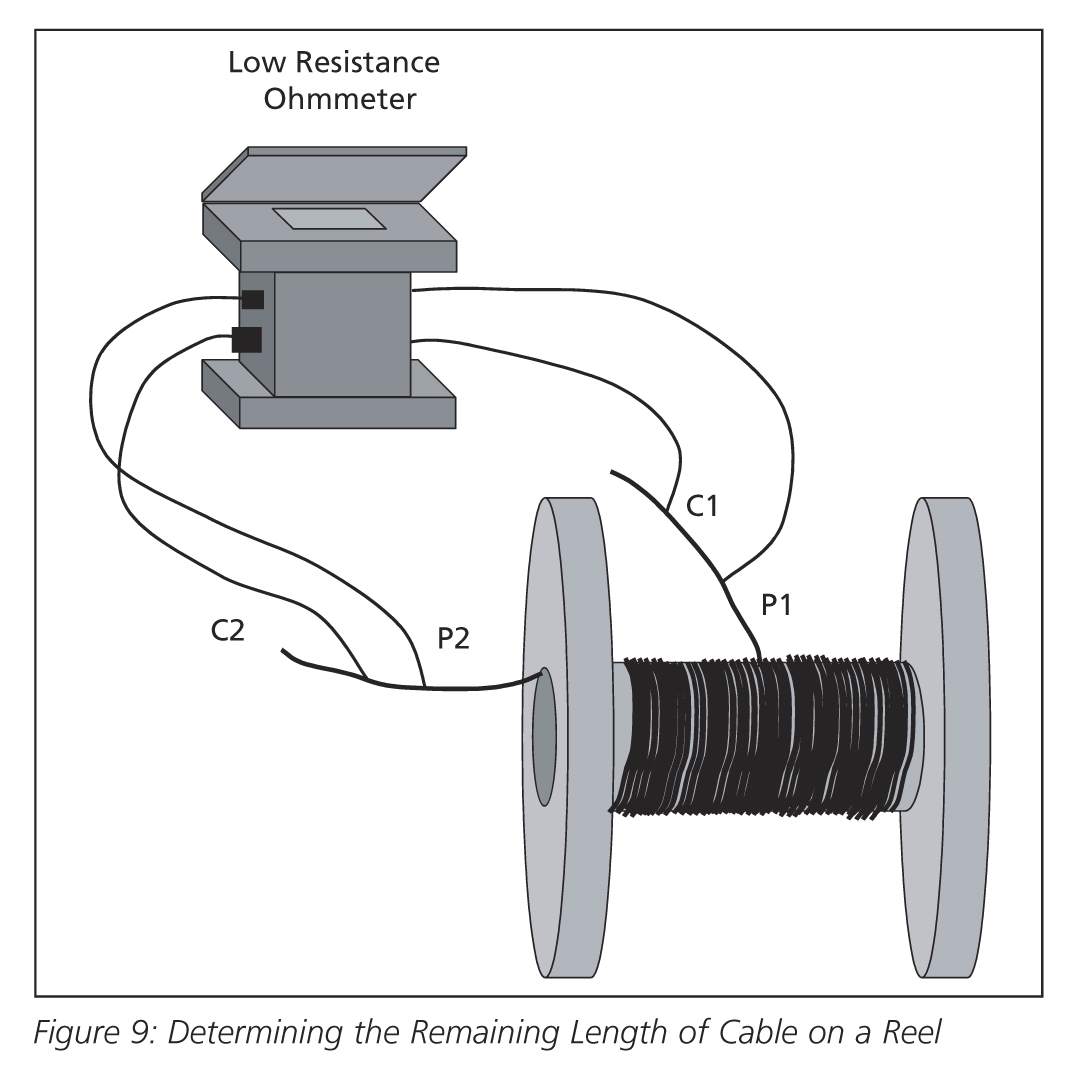 Cable Reels – A reel of insulated copper wire may have a tag indicating the wire gauge along with the ohms per unit length. When wire remains on the reel after partial utilization, the remaining length can be calculated by measuring the resistance of the wire and making a calculation using the ohms per length specification (see Figure 9).
Alternatively, if the tag has been destroyed, the operator can cut off a known length of wire, measure that sample and determine the ohms per length. This value can then be used with the reading taken when measuring the balance of wire on the reel to calculate the remaining length. The temperature of the reel of cable will be approximately the same as the temperature of the sample. Though the internal temperature of the reel may be slightly different, a reasonable estimate of the remaining length of cable can be calculated.
If the operator reviews the temperature charts on pages 18 and 19 in this book, an estimate of the inaccuracy can be determined. This method also applies to aluminum and steel wires as long as the wire has an insulating coating to prevent shorting between adjacent loops of wire. Download the complete article “Guide to Low Resistance Testing”
Megger DLRO10HD 10 Amp Digital Low Resistance Ohmmeter
JM Test Systems now carries the Megger DLRO10HD Low Resistance Ohmmeter.
- High or low output power selection for condition diagnosis
- Rechargeable battery or line power supply, continuous operation, even with dead battery
- 10 A for 60 seconds, less time waiting to cool, great for charging inductance
- High input protection to 600 V, inadvertent connection to line or UPS voltage will not blow a fuse
- Heavy duty case: IP65 lid closed, IP54 operational (battery operation only)
- Rotary switch selects one of five test modes, including auto start on connection, giving ease of use

Download the complete Data Sheet and Comparison Chart for the Megger DLRO10HD
JM Test Systems is a Stocking Distributor of Megger products
JM Test Systems has the Megger DLRO10HD for purchase
Rent the Megger DLRO10HD from JM Test Systems
Call us today for a quote at 800-353-3411 or check us out on the web at www.jmtestsystems.com
Calibration Service – Since 1982 JM Test Systems has been providing NIST traceable calibrations to our customers. We are dedicated to a single goal: provide the best possible service for both our products and our customers.
ISO/IEC 17025 Accredited by A2LA ISO/IEC 17025 accreditation is your assurance that our work meets the highest standards.
