

Why Soil Resistivity Matters
Before designing or installing a grounding system, the first step is to measure the soil resistivity. Soil resistivity directly affects how electricity flows into the ground, which is critical for safety, reliability, and performance in electrical systems. This critical value determines how effectively a grounding electrode can dissipate fault current into the earth. Low soil resistivity means current can dissipate easily, creating an effective grounding system that protects people and equipment from electrical faults, lightning strikes, and static charges. High soil resistivity, on the other hand, makes it harder to achieve safe grounding, potentially leading to dangerous step-and-touch voltages, equipment damage, or unreliable protective devices. Soil resistivity measurements have three important purposes:
- Supporting geophysical surveys to identify ore locations, bedrock depth, and other geological conditions.
- Assessing pipeline corrosion risk, since lower resistivity accelerates corrosion.
- Guiding the design of grounding systems, where the goal is safe, low-resistance paths to earth.
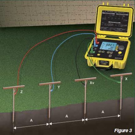
Using instruments such as the AEMC 6471 or AEMC 6472 (for 4-point testing), engineers can collect accurate resistivity data. With this data, the required depth of ground rods can be calculated using a Nomograph in just six simple steps.
Step 1: Select the Required Resistance on the R Scale
The first step in grounding system design is determining the target ground resistance value. This will depend on the application, system voltage, and applicable codes or standards. Once the resistance value is chosen (for example, 5 ohms), locate it on the R scale of the Nomograph. This provides the benchmark against which soil resistivity and rod installation depth will be calculated.
Step 2: Select the Measured Soil Resistivity on the P Scale
Next, use the results from your soil resistivity test-expressed as ρ (rho) in ohm-meters-and find the corresponding value on the P scale. Resistivity can vary widely depending on soil composition, moisture content, and temperature. Identifying this value is essential, since it directly impacts how deep and how many rods are needed to achieve the desired ground resistance.
Step 3: Connect the R and P Scales to Intersect the K Scale
Using a straightedge, draw a line connecting the selected resistance on the R scale with the soil resistivity on the P scale. Extend the line until it intersects the K scale on the Nomograph. This intersection represents a calculated constant that factors both your soil resistivity and desired resistance into a single reference point.
Step 4: Mark the Intersection on the K Scale
Place a dot at the point where your straightedge intersects the K scale. This marked point will serve as the anchor for determining the required installation depth of the grounding electrode in later steps. This step essentially captures the relationship between soil conditions and the system’s grounding requirements.
Step 5: Select the Ground Rod Diameter on the DIA Scale
Locate your desired rod diameter on the DIA scale of the Nomograph. Ground rods typically come in standard diameters, such as 5/8 inch or 3/4 inch. Mark this point clearly on the scale. The chosen diameter influences the contact surface area between the rod and soil, and therefore affects the resistance-to-earth performance.
Step 6: Draw a Line Through the DIA and K Points to Find Depth
Finally, align your straightedge through the marked point on the DIA scale and the point you plotted earlier on the K scale. Extend this line until it intersects the D scale. The point of intersection on the D scale indicates the required depth for the ground rod installation to meet the target resistance. This depth ensures your grounding system performs safely and effectively under fault conditions.
Measuring Soil Resistivity: Wenner vs. Schlumberger
To obtain accurate soil resistivity values in the first place, two common test methods are used:
- Wenner Method: Most popular for grounding electrode design, simple to implement with four electrodes placed in-line and equally spaced.
- Schlumberger Method: More practical for geological surveys when measuring resistivity at multiple depths.
Both methods calculate resistivity (ρ) in ohm-meters using the voltage and current measured across the electrodes. For grounding system design, the Wenner method is typically used, as it provides reliable data for calculating rod depth and placement.
Recommended Instruments for Soil Resistivity Testing
For accurate and reliable soil resistivity measurements, JM Test Systems recommends:
- 4-Point Testing: AEMC 6471 & AEMC 6472 (capable of advanced resistivity and grounding system analysis).
- 3-Point Testing: AEMC AEMC 3640, AEMC3 620, AEMC 4630, AEMC 4620, and 6470 models.
These instruments provide the precision needed to design grounding systems that comply with electrical safety standards while minimizing material costs.
Conclusion
Designing an effective grounding system begins with understanding soil resistivity and calculating the correct rod depth. By following these six steps with a Nomograph, engineers can confidently size and install grounding electrodes to achieve the desired resistance.
At JM Test Systems, we provide a wide range of ground resistance testers, soil resistivity meters, and calibration services to ensure your grounding system is designed and verified to the highest standards. Call 1-800-353-3411 for expert support on ground testing equipment and services.
